| g e n u i n e i d e a s | ||||||
 |
 |
 |
 |
 |
 |
 |
| home | art and science |
writings | biography | food | inventions | search |
| back and forth |
| Mar 2015 |
|
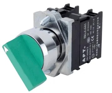
Rotary joints are problematic. They add friction. Wear out. And worst of all, leak. But in some limited cases there is a solution. When the axle's motion is oscillatory rather than purely rotational, a bellows can twist back and forth, maintaining a perfect seal. If the bellows does not kink or over-stress, it will not leak for the life of the product1. Such a bellows might useful in a rotary electrical switch:
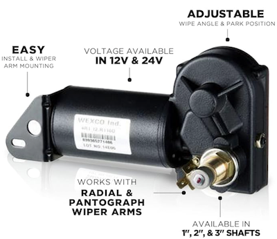
Or in an oscillating motor, like in a window washer:
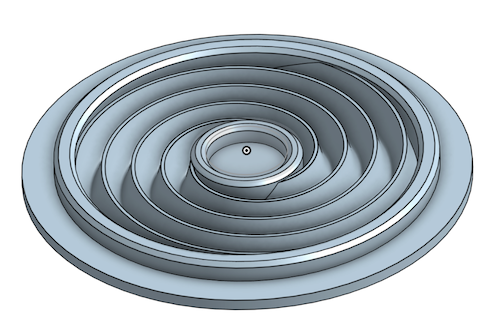
Providing there is room, an easy solution is to make the bellows out a floppy "bag" of elastomer. As long as the bag has enough slack and room to move without binding, the axle can spin back and forth without tightly kinking the bag. And kink it may- when the axle turns it twists the bag, forcing an origami-like network of folds to appear. Stresses are high where folds meet at a point, and over time, this corner may creep, work-harden and break open. A molded bellows avoids high stresses by controlling the bending, providing there is sufficient room along the axle for a long bellows. In this case, one section of the bellows is pre-twisted, narrowing at the center as it rotates. Like an iris in a camera. But this also shortens its length, and will bind as a result. So a twisted bellows must be combined with a conventional annular bellows, which does not twist but can adjust in length. As seen in this video: In many applications, space is limited and a planar solution is advantageous. Sufficient "slack" must be incorporated to compensate for the axle winding up the bellows as it turns. Thus a planar bellows must be slightly extended into the third dimension. The obvious solution is a spiral bellows, but experiment proves a spiral bellows kinks uncontrollably, and the kinks are failure points.
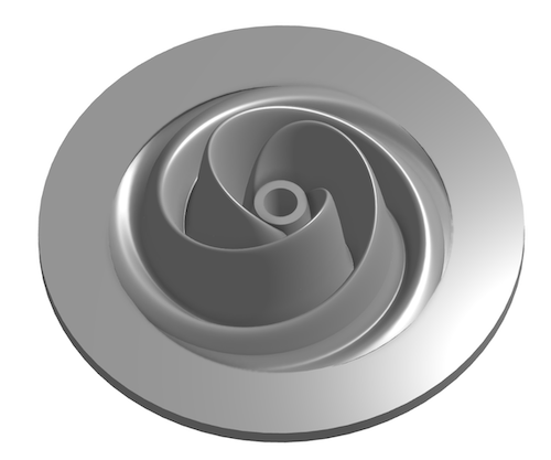
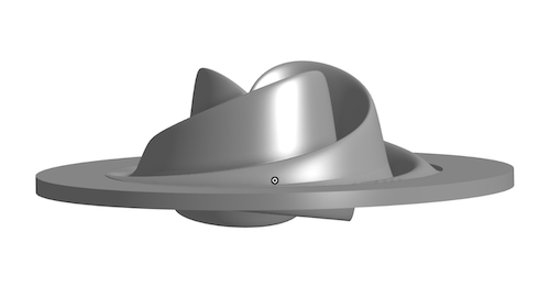
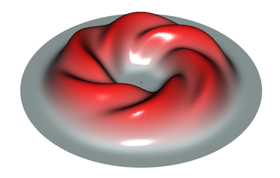
Our solution is to break perfect spiral symmetry in order to control the loction of any incipient kinks. Many designs are possible, but after some modeling and experimentation2, a rose-petal like design works well and is easily moldable. It also permits a bit of translational motion in the plane, as well as tilt around the center point. Here is one version:
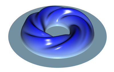
Note how the peaked ramps force any kinks to smoothly distribute along the spiral, eliminating high stress points. This example oscillates from 0 to 90 degrees:
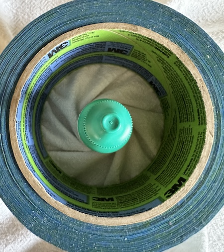
To create these prototypes I printed 3D molds and compression-molded with uncured silicone rubber. The mold is designed to thicken the rubber along the peaks and valleys of the spiral, providing extra stiffness against kinking. Mathematically, the surface may be described in cylindrical coordinates as
where
Though other functions are possible3, this choice is compatible with many CAD programs. When the bellows is relatively flat (e.g. small "C", and thus little slack), the elastomer is highly stressed when twisted, so acts like a torsion spring. OTOH, when the rose bellows has deep "petals" in the Z direction, springiness is reduced or eliminated. Trading off volume against lifetime. Three rose petals seem optimal for 90 degree oscillation, but that conclusion depends on elastomer thickness, stiffness, etc.
|
|
1 Unless magnetically coupled. 2 This design was inspired by twisting a sheet of paper or cloth, and mimicing the naturally occuring folds.
3 A few alternate driving surfaces.
z=exp(-(r-2)^4)*(1+.2*cos(6θ+4r))
z=sqrt(1-(r -2)^2)*(1+.2*cos(6θ+6r))
|
Contact Greg Blonder by email here - Modified Genuine Ideas, LLC. |