| g e n u i n e i d e a s | ||||||
 |
 |
 |
 |
 |
 |
 |
| home | art and science |
writings | biography | food | inventions | search |
| an angle on design | |||||||||||||||||||||
| May 25, 2015 | |||||||||||||||||||||
|
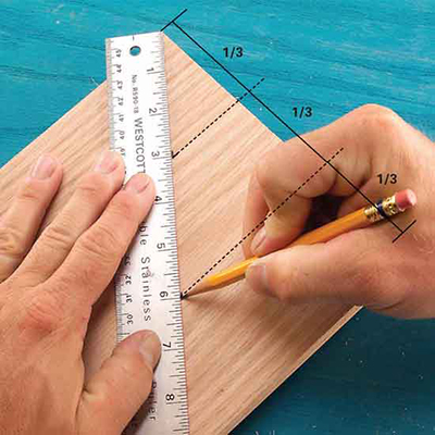
Design and engineering students are mesmerized by their computer tools, and rightly so. Almost anything you dream of can be modeled, tested and simulated. Even the most fanciful shapes can be prototyped in software and brought to life by computer-controlled machines. But, the reliance on CAD systems has atrophied these future engineer's mechanical intuition. You can easily select a plastic formulation from a pull-down menu of hundreds of alternatives, and then simulate its properties in operation. But only though direct tactile experience do you know which plastic feels "hard" and rings when tapped, and which will shatter if drilled too aggressively. So I wanted to spend a day teaching design without the benefit of CAD. Hell, even without long division. And rediscover a more intuitive design methodology: For centuries, journeymen carpenters rarely enjoyed the benefit of formal schooling, and many were illiterate. Yet geometry is at the heart of their profession. So they developed thousands of "tricks" and shortcuts to layout a project without resorting to math. For example, how would you divide a 10 11⁄16th wide board into three equal planks? Dividing the width by three, and then trying to locate 3 9⁄16 and 7 1⁄8 on a ruler is fraught with error. Instead, they laid a ruler on the board at an angle, and chose three equally spaced integer dimensions to split the width:
(from Family Handyman)
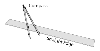
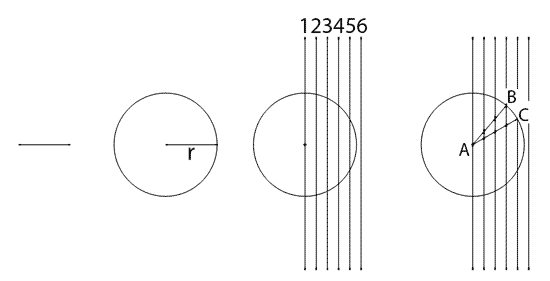
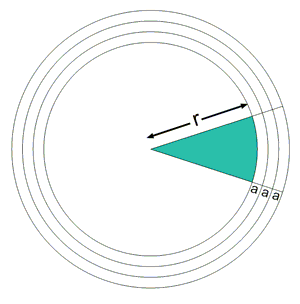
Carpenters were also familiar with the compass and straight edge, and devised many related techniques to divide a cabinet layout line into equal segments. First, they ruled a series of equally spaced lines (1,2,3 ...) - their exact periodicity was not important. Then, they set their compass to the length of the layout line "r". By drawing a circle of radius "r" over the parallel lines, that radius was divided into equal segments, depending on how many lines it exactly intersected. In this case, three segments for radius AB and four segments for radius AC.
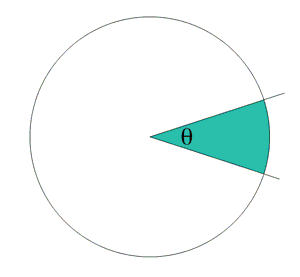
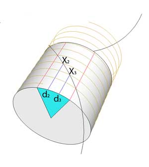
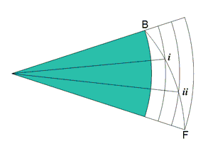
In woodworking, dimensions are often transfered from one surface to another by scribing. For example, to align a dove tail joint around a drawer corner, the front and sides are clamped together and the layout lines are scribed through- no measuring, no chance for numerical error. Similarly, before turning on a lathe, profile shapes are transfered from the lumber's edge, to the faces of a nascent table leg. So I wondered if a similar trick could be used to divide an angle into three equal sections with just a compass and a straight edge (I'm not sure why I connected the dots-- this part was pure intuition -- and the last time I thought about the problem was in high school geometry). Trisecting an angle is an old, well worn mathematical challenge that has bedeviled geometricians since the time of the ancient Greeks. Mostly because the trisection of the angle with compass and straight edge is impossible (as first proved by Pierre Wantzel in 1837). But that proof applies to the plane- what if the angle could be split by adding a third dimension?
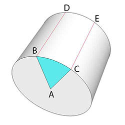
Often, moving to a higher dimension simplifies a problem. For example, knotty mathematical equations can often be solved by embedding those equations in the complex plane. Or, as President Eisenhower suggested in politics- "If a problem cannot be solved, enlarge it." As it turns out, moving from the plane to a three dimensional surface often eliminates the need for a compass. For example, a straight line on the surface of a globe is a "great circle of latitude", and is visible as a circle when viewed by those of us trapped in the third dimension. No compass is required to "draw" a circle, if that circle girds a sphere. Straight lines-- which are the shortest distance between two points-- appear to be a spiral, circle or a lateral seam (like EC) on a cylindrical surface1. This higher order geometry breaks the constraint Wantzel identified in the plane. By drawing on a cylinder, the straight edge alone suffices, and the intersection with carpentry tricks a tight fit.
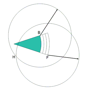
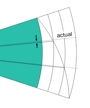
Of course, we "cheated" by entering the third dimension, but the method is simple and effective. You might wonder if the cylinder could somehow be "mapped" back to a flat piece of paper, and if so, would it would perform nearly as well. And "nearly" is correct. A rudimentary mapping trisects the angle pretty accurately, leaving an error which is small but visible:
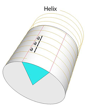
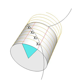
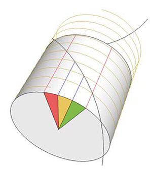
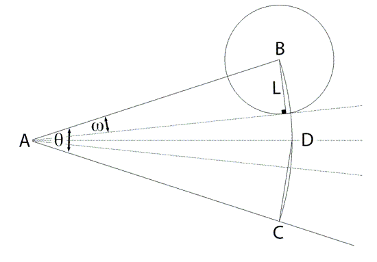
But this is not the end of the story. As is often the case, while working on the drawings for this short note, I added some other guide circles, and noticed a different construction was more accurate. MUCH more accurate. Chance favors the prepared mind. Undoubtedly, this construction is well known to trisection cognoscenti (and you know who you are), but here is what I discovered late that night:
Expanding this equation via a Taylor Series, the first term is a perfect trisection. The second term, basically the error, is third order in θ! So quite small. For example, if θ is a 30 degree angle, the error is only 0.02 degrees. Less than a pencil line thickness. So this method is both simple and highly accurate. How would a carpenter trisect an angle? If they had to divide angles every day at work, they would buy or make a pantograph with four arms linked together, so the tips mechanically split the angle exactly. But, in under fifteen seconds, you can simply guess at the right chord length for a trisected angle, adjust a divider to that length, swing it along arc BC, and readjust if it misses the mark. A few quick iterations and the angle is divided in three, more accurately than it can be cut with a saw. And somehow more satisfying than moving a cursor on a screen.
|
|||||||||||||||||||||
|
---------------- 1 The famous "fly on the wall" puzzle by Dudeney is a classic example where a straight line solves a 3D puzzle by flattening to a plane. 2 If you slightly shift the origin of the concentric circles by an amount proportional to θ, so they follow more a helical trajectory through the angle, and then draw the intersection arc, the trisection is very accurately determined. This offset can be "calculated" geometrically, but to my mind, violates the spirit of this challenge.
|
|||||||||||||||||||||
Contact Greg Blonder by email here - Modified Genuine Ideas, LLC. |